


Description
High performance intakes for N63TU2 (pre-LCI) M550i vehicles (2018-2019). Also known to fit LCI G12 750i vehicles.
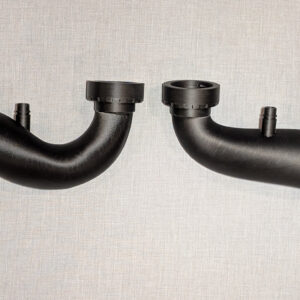
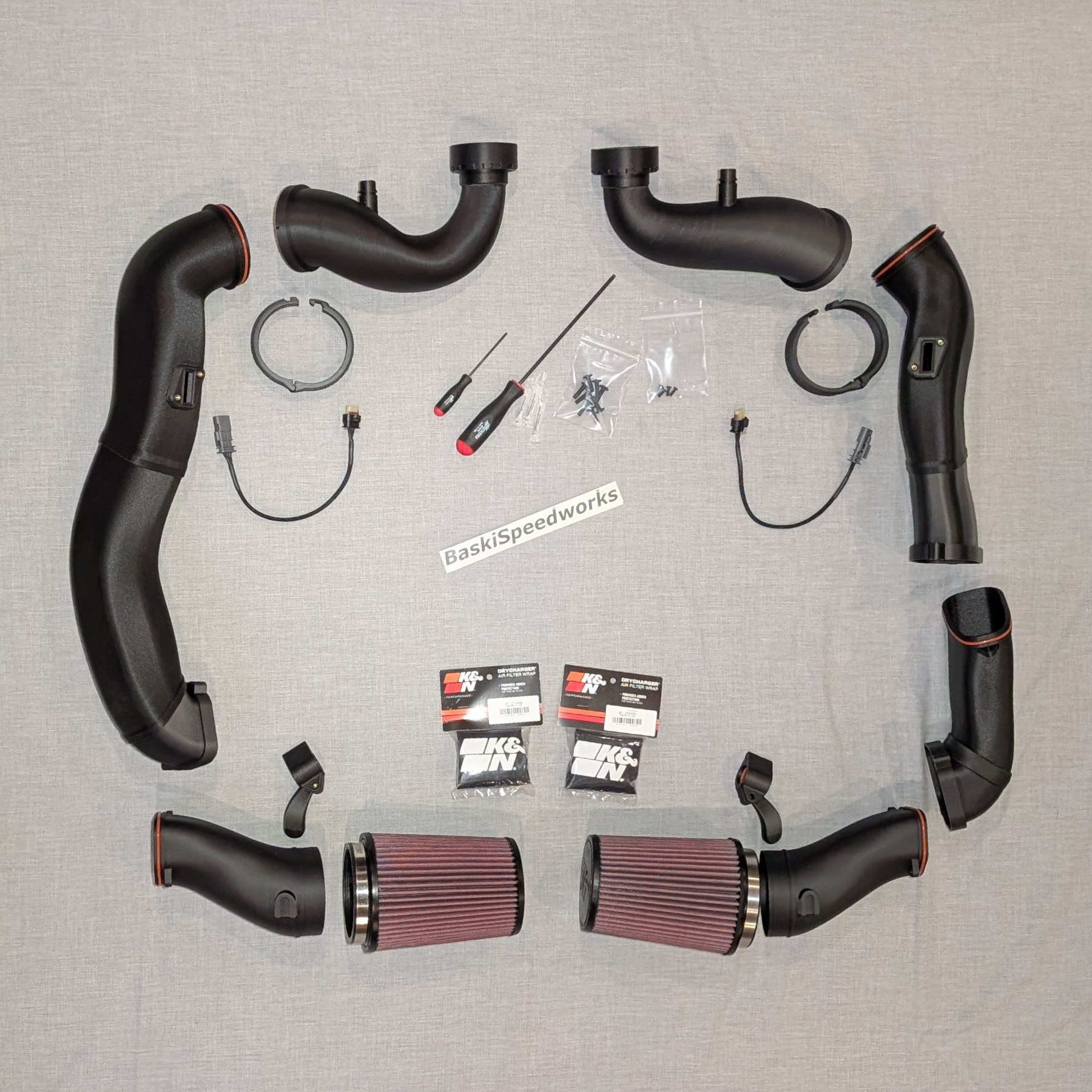
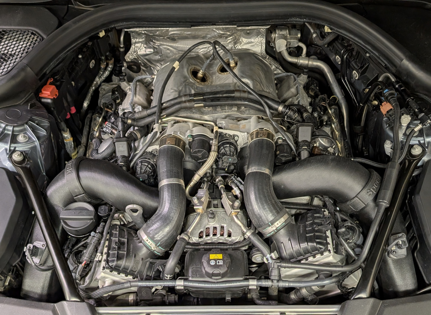
The cross section of the intakes, from the filter up to the inlet is the equivalent of 3.5″ tubing. Intakes are a three piece design for bank 1: filter adapter, main intake section, and inlet, with O-rings to seal each joint. Bank 2 is a four piece design to accommodate the drive’s side AC line that blocks part of the opening through the front bulkhead. Intakes are 3D printed from three different types of carbon fiber infused material (PAHT-CF, PET-CF, and PPA-CF). Inlet material is rated to withstand temperatures up to 440 degF.
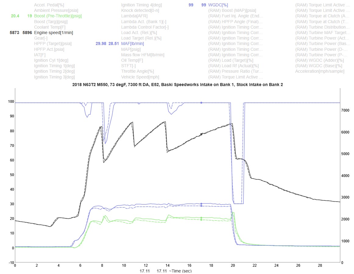
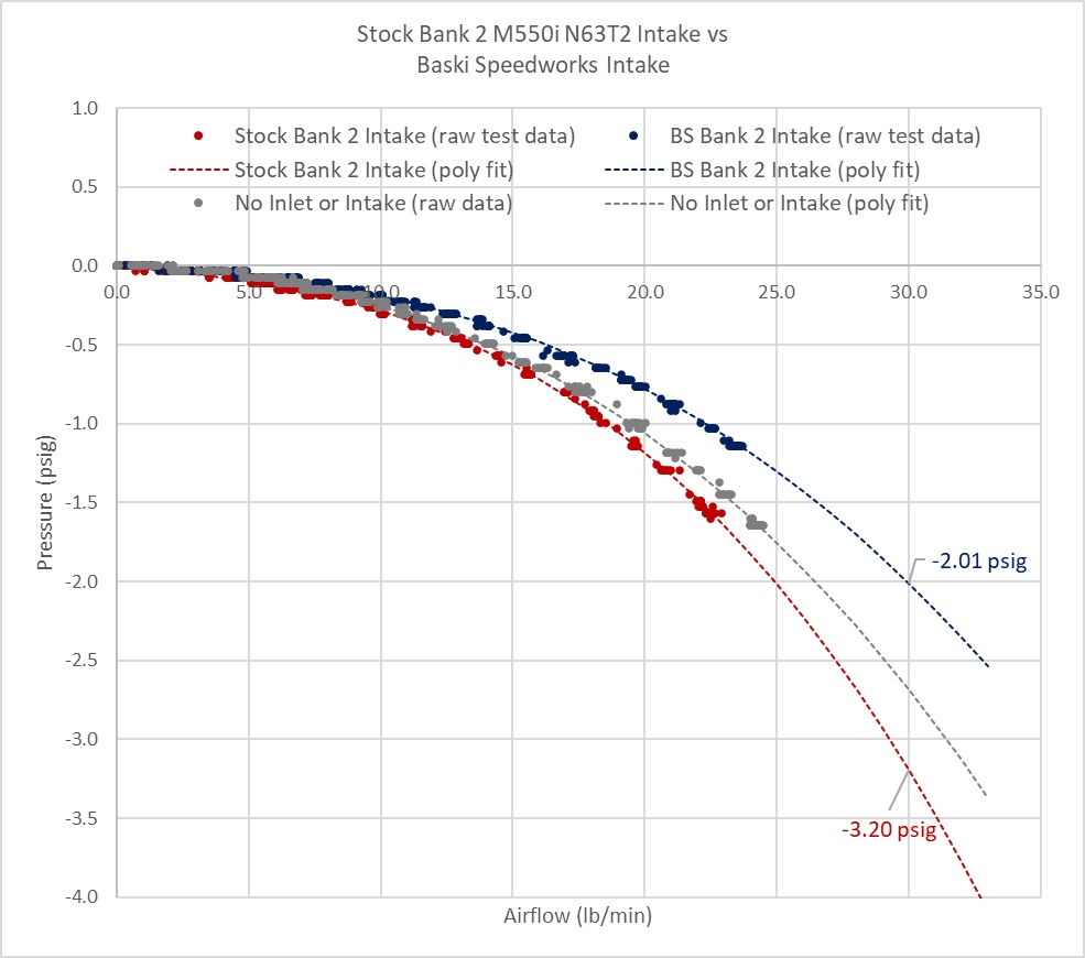
The intakes are good for 1.0-1.5 psi of boost compared to stock intakes (i.e. less flow restriction), as shown in the log where bank 1 was running the new intake and inlet and bank 2 was stock N63TU2 intake and inlet (this is at 7000 ft DA, where stock TU2 turbos can barely make 20 psi of boost). Static airflow test results shows similar reduction in flow restriction. Dragy results typically show a half second improvement from 60-130 mph or 100-200 kph, as shown in the Dragy screenshots where a car with TU3 turbos, WMI, and E50 fuel improved its 100-200 kph time from 6.56 seconds to 5.97 seconds with just the intake change (both runs were at the same boost level of 28 psi). The log data for that car shows WGDC dropped from 79% WGDC to 67% WGDC. These results show that the intakes are capable of power gains of 40-60 HP at the crank (30-50 at the wheels).
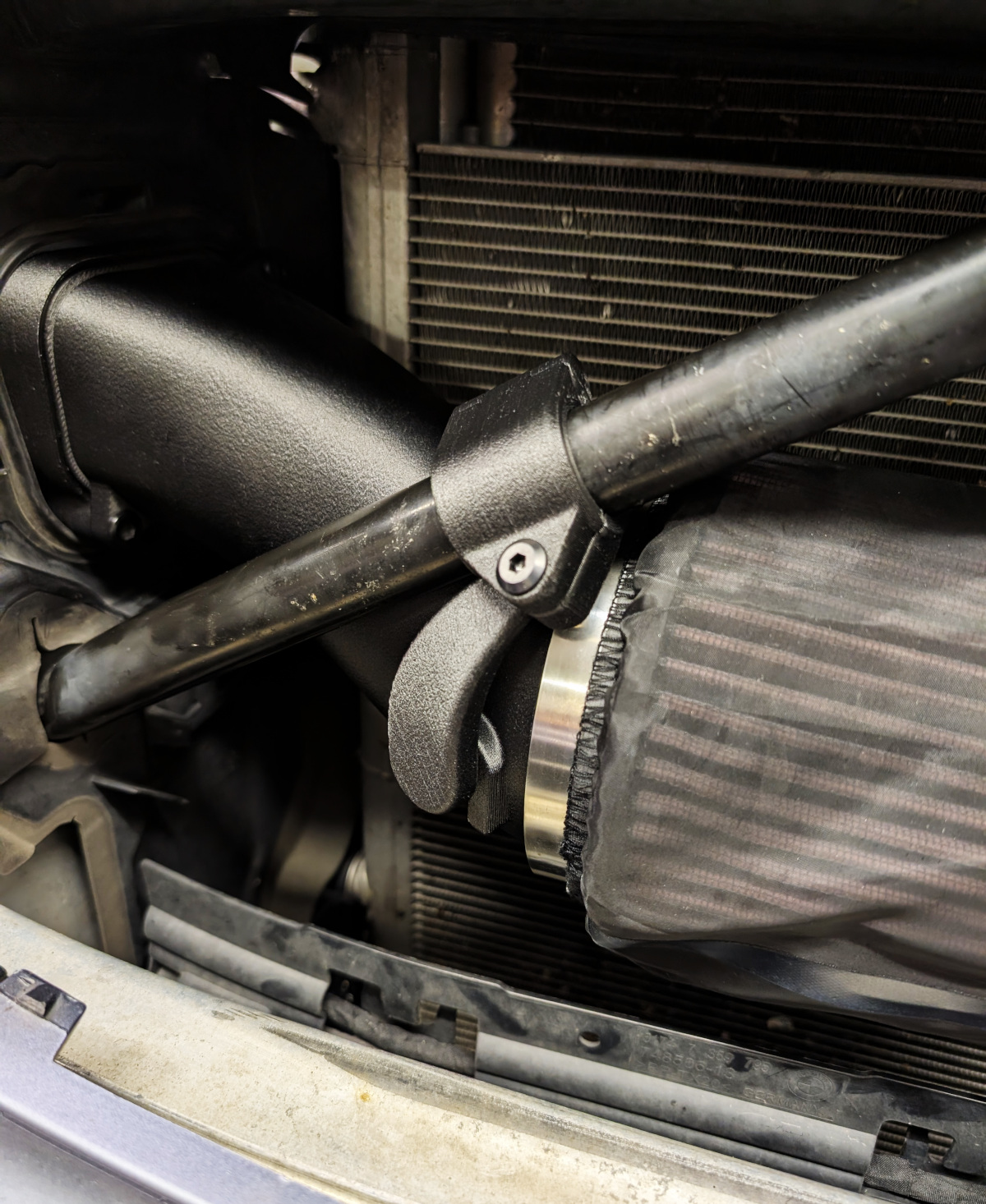
Inlets attach to stock PCV system and allow use of the stock diagonal strut tower braces. Filters fit behind stock grilles (no cutting or other modifications needed). Air filters, filter covers (which greatly extend the service life of the filters and have no impact on performance), MAF sensor extension cables, and inlets for either TU2 or TU3 turbos are included. TU3 turbo inlets can be purchased separately in the future.
Installation takes 4-6 hours and requires temporary lowering of front bumper and removal of grille shutters and headlights. These intakes are designed for maximum performance and low weight, and need to be installed with some care and thoughtfulness. During installation, parts do not need to be forced and screws do not need to be tightened more than hand tight with the supplied hex screwdrivers. Professional installation by a shop with BMW vehicle experience is recommended.
No tuning changes are typically necessary (with the 3/31/2026 updated design), but they may be needed depending on other mods on the vehicle and the fuel.
The intakes are designed, manufactured (3D printed), and assembled in the USA.
Installation steps:
- Pull charge pipes off turbos (leave the intercooler ends connected)
- Remove diagonal braces that attach at the strut towers
- Remove stock filter housing and turbo inlets
- Drop front bumper (doesn’t need to be fully removed, but dropped a few inches)
- Remove headlights
- Remove active shutter grille
- Remove stock intakes (there is screw on each bank that attaches the intake to the vertical support next to the headlight cavity)
- Detach electrical connector holders for rear O2 sensor wiring from plastic plates on top of the valve covers and move connectors to the side (so the intakes sit lower where they pass over the valve covers)
- Insert passenger side intake through the intake opening (with careful rotating and wiggling it should slide into place with minimal force)
- Grease the inside of the end elbow on the intake and attach filter adapter to it using the supplied bolts and hex screwdriver
- Grease turbo inlet seal with supplied grease
- Attach inlets to the turbos, using a flathead screwdriver to lock the rotary attachment ring
- Grease PCV ports on the inlets and attach PCV hoses
- Grease inside of inlet ends where the intakes with their O-rings will be inserted
- Attach intakes to the inlets with the tension clamps (squeeze until they snap closed)
- Slide the filter adapter holder onto the filter adapter and attach it to the cross brace in front of the radiator – the filter adapter should fit loosely on the holder and move freely up and down at least 1/4″
- Slide the filter cover over the filter and attach the filter to the filter adapter with the hose clamp
- Intake installation is the same on the driver’s side, except the intake main section is comprised of two sections, and the inside of the upper intake section needs to be greased before inserting the lower section
- Insert MAF sensors into the housings on the intakes and attach with provided screws and hex screwdriver
- Connect MAF sensors using the provided MAF extension cables
- Reinstall active shitter grille, headlights, and bumper
- Pull the vertical section of fuel tank vent line from the holders on the side of the engine bay, move it towards the front of the engine, and fasten to the vertical section of fuel line (with velcro or zip tie) so that the tank vent line sits to the side of the intake clamp with clearance to the hood
When installed, there should be at least a 1/4″ gap between the diagonal strut brace and the top of the intake on each bank (the intake should move relatively freely under the brace). If the brace is pressing against the intake, check that the electrical connector for the rear O2 sensor on top of the valve cover under the intake is fully detached and moved to the side. This video shows how much play there should be in the intakes after installation (this is needed to allow for engine movement): G30_M550_Intakes_After_Intall.mp4
To remove tension clamps, pry open with a flathead screwdriver in the slot where the two ends of the clamp meet.
To remove the inlets, rotate the lock by hand or with a flathead screwdriver. Inlet_Rotary_Lock_Video.mp4
Detailed installation instructions are here: G30_N63TU2_M550i_Intake_Installation_Instructions.pdf